Magnetic fluid feedthrough primer — page 2/4
- Basic sealing principle
- Design improvements
- "SuperseaL" - A breakthrough in feedthrough design
- Application factors
- Impact of feedthrough on process
- Impact of process on feedthrough
- Materials considerations
- Application examples
"SuperseaL" - A breakthrough in feedthrough design
Researchers have found a way to simplify and further improve the design of fluid sealed feedthroughs. Figure 3 illustrates the SuperseaL concept.
Two opposed-polarity magnets are placed within the rotating shaft and the housing (made of ferromagnetic material) is an integral part of the magnetic circuit. A number of carefully formed grooves on the surface of the shaft determine the location of the fluid sealing rings. Because the shaft diameter is larger than the bearing journals in the region containing the magnets and grooves, there is no loss of strength as a result of using a grooved shaft.
The magnets are embedded in a matrix of ferromagnetic shaft material, which acts as a magnetic shunt. The casual observer may think this would weaken the magnetic field in the fluid seal region, leading to a very weak seal. However, the reality is that by proper selection of materials and careful design, it is possible to make SuperseaL feedthroughs with very high pressure capacity.
Benefits of the SuperseaL design are:
- Requires fewer parts
- Provides better alignment between seal components
- Permits extremely low external magnetic field because housing is magnetic
- Uses no internal static seal (O-ring), thereby eliminating a potential source of leakage
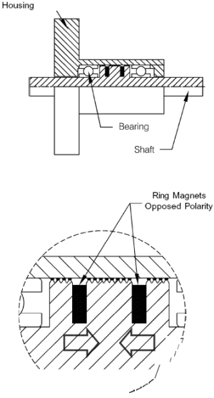
Figure 3
The SuperseaL design is protected by United States and International patents.
In some applications, it is desirable to use a separate pole piece. Here a related design, called SuperseaL II, can be used. Figure 4 shows a pole piece machined from a single piece of magnetic stainless steel, with small internal grooves to define the fluid regions. The shaft is smooth. Magnets are mounted in deep internal grooves. This design minimizes the number of parts required to produce a separate pole piece. Because the housing is not part of the magnetic circuit, an O-ring is required for static sealing of pole piece to housing.
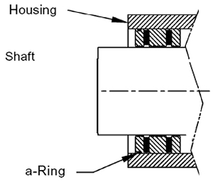
Figure 4
Application factors
Magnetic fluid feedthroughs are appropriate for many applications, but it is important to consider two groups of application factors when selecting a specific model for a particular application. Environmental factors always include process operating pressure and ambient temperature, and may include other process-related factors as well. Mechanical factors include speed, loads (radial and thrust), duty cycle, and bearing ratings.
Environmental factors
Figure 5 shows some broad operating guidelines for process pressure and feedthrough temperature. Water cooling (or heating) extends the useful temperature range. Units can be designed for use at high pressure.

Figure 5
Temperature limits are based on the properties of magnetic fluids and other construction materials. Although rarely encountered, low temperatures can increase fluid viscosity sufficiently to require unacceptably large driving torque. High temperatures cause deleterious chemical and physical changes in fluids and other materials.
Pressure limits are determined by magnetic design and fluid properties. The lower limit is set by the vapor pressure of the base liquid (temperature dependent) in combination with the process tolerance for fluid vapors. Higher pressure ratings can be achieved by adding more stages. Standard products offer maximum pressure capacity of as much as 2.4 atmospheres (2.4 kg/cm²).
In cases of high-speed operation, the self-heating of the viscous magnetic fluid becomes a significant cause of elevated temperature. Surface speeds up to 7 m/sec are possible without water cooling (DN= diameter x rpm =120,000 mm-rpm). With water cooling, surface speed can be increased to about three times this value.
Mechanical factors
Except for light-duty applications, mechanical operating factors have great impact on the performance and lifetime of feedthroughs. Wholly apart from vacuum considerations, bearings and shafts must support each application's requirements for speed, load, duty cycle, torque transmission, end play, and so on. Thorough consideration of these factors is beyond the scope of this discussion, but a few key points can be mentioned here.
Shaft sizes must be large enough to transmit the required torque from motor to load over the full range of anticipated acceleration and speed. Possibilities of jamming should be taken into account.
Bearings must be rated to handle the radial and axial loads to be experienced in service. Significant tradeoffs exist between radial load, axial load, operating speed, duty cycle, operating temperature, lubrication, and bearing lifetime. Thus, any "load rating" of a feedthrough as a single number cannot be an adequate characterization over a realistic range of applications. Users should be aware that bearing lifetime varies strongly with load and speed, according to the following equation:
LIO = [A(C/P)³]/N
where:
-
LlO = bearing life expectancy (90% confidence)
-
A = lubrication factor (normally less than 1)
-
N = operating speed, RPM
-
C = "dynamic load rating" of the bearing (depends on bearing size)
-
P = "dynamic equivalent load" (combination of radial and axial loads)
The main point to note from this equation is that bearing life varies linearly with rpm and exponentially (as the third power!) with load and rating. Loading the bearings beyond their rating leads to very rapid failure.
As a practical matter, selection of appropriate models can often be guided by previous experience in similar applications. We should be consulted for recommendations and application assistance in selecting feedthroughs for unusual applications.
Ask for more information about our feedthrough products:
Copyright © 2022 – Rotary Vacuum Products. All rights reserved.