Magnetic fluid feedthrough primer — page 4/4
- Basic sealing principle
- Design improvements
- "SuperseaL" - A breakthrough in feedthrough design
- Application factors
- Impact of feedthrough on process
- Impact of process on feedthrough
- Materials considerations
- Application examples
Application examples
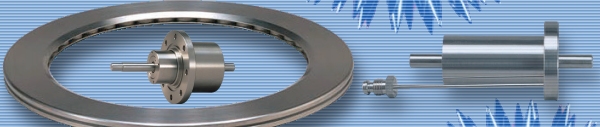
Light-duty feedthroughs
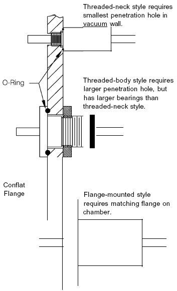
Examples of this category include shutters for evaporation and sputtering deposition sources, positioning systems for multi-pocket E-beam evaporation sources, sample positioners, and chopper wheels. Shaft diameters are typically 6 mm to 10 mm. Figure 6 illustrates three mounting styles for popular products with 6.35-mm shaft diameter.
|
|
|
Figure 6: Light-duty feedthroughs, 6.35 mm shaft diameter |
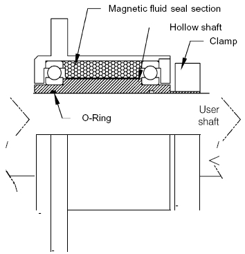
Hollow-shaft seals
In applications where shafts are large, complex, proprietary, or subject to design revision, hollowshaft feedthroughs can often be used to advantage. Hollow-shaft feedthroughs provide a complete bearing and seal package in which the shaft is a tube or sleeve with closely controlled inside diameter. Thc user joins this package to the shaft to form a complete assembly suitable for the application. A static O-ring seal between the hollow shaft LD. and the user shaft O.D. is required. Some positive means of driving the hollow shaft via the user shaft is required to ensure that the user shaft does not move relative to the hollow shaft, an event that would damage the static O-ring seal. Figure 7 illustrates the typical case.
 |
|
Figure 7 |
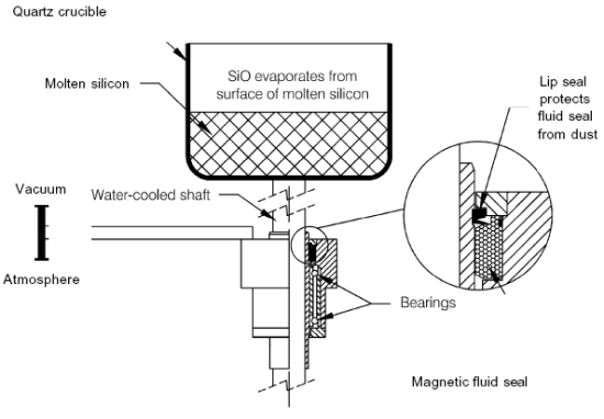
Crucible rotation seal for Czochralski silicon crystal puller
Figure 8 shows how a magnetic fluid feedthrough is used in a process that generates a great deal of finely divided dust (SiO) that would rapidly degrade bearings and seal. A cantilever bearing design separates bearings and process, and a lip seal isolates the magnetic fluid seal from the process, increasing the number of process cycles that can be run before the seal must be serviced. During the crystal growth process, the operating pressure is maintained at about 20 torr by flowing argon through the process vessel. This is well above the high-vacuum range. However, the process IS very sensitive to oxygen and nitrogen, so sealing must be of the same high quality as in high-vacuum systems. This is a custom-designed product.
 |
|
Figure 8 |
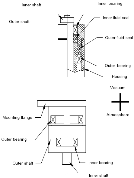
Coaxial feedthrough for robotic arm
Robotic arms are widely used to handle silicon wafers and fiat-panel displays in cluster tools and other semiconductor processing equipment. Two independent motions are required. One method of achieving this is to nest one feedthrough inside another, as illustrated in Figure 9. The outer shaft is supported in the housing by bearings near the bottom and top ends. The outer fluid seal is outside the vacuum space, making this a cantilevered design. The inner shaft is supported within the outer shaft by another set of bearings. In the case shown here, the inner shaft bearings are in the straddle configuration, with the upper bearing in the vacuum space. Products of this degree of complexity are always custom-designed. Our engineers must work closely with the customer's design team on this kind of project.
 |
|
Figure 9 |
Primer written by Walter Helgeland in April, 2002
Ask for more information about our feedthrough products:
Copyright © 2022 – Rotary Vacuum Products. All rights reserved.